Search this site (www.microchipC.com).


CCS C Compiler for Microchip PIC micros

Your ad here


PIC and Hi-Tech C FAQ

The experience for this FAQ taken from a degree in Electrical Engineering (Beng. Elec. Hons.), at University of Canterbury, tutoring students for a 4th year Canterbury University Electrical Engineering design course, and 8 years commercial programming with PIC micros.

Last updated 23rd February 2010.

This FAQ contains the top 68 questions and techniques asked by PIC micro students about Hi-Tech C for the PIC16Fx, PIC18Fx and PIC24Fx micros from the University of Canterbury.

View the latest questions and answers on www.MicrochipFault.com, under the tag:

This FAQ contains over 100k of pure text.

Enjoy – I sincerely hope this advice saves you a lot of time and effort.

Fundamentals of PIC and Hi-Tech C

Q. What are the most commonly used features of a PIC micro?

Q. So, how do I use the features listed in the previous question?
Q. Tell me how to drive the pins on a PIC micro

Researching Data


Q. How do I find suppliers of Microchip parts?
Q. How to I do research on a new project?

"... I work for Flinders University and we hand out your Hi-Tech PICC FAQ to our students. Thanks for your work there."

Craig Peacock
www.beyondlogic.org

Tips for using features of C on a PIC micro

Q. How do I express numbers in decimal, hexadecimal or binary?

Q. Whats wrong with the following code …?
Q. What datatypes are available on a PIC?
Q. How do I switch bits on and off in a variable?
Q. How do I test bits in a variable?
Q. How do I divide or multiply by two efficiently?
Q. How do I reference one of the bytes in an integer?
Q. Doesn’t ‘x>>=8’ have 8 shifts?
Q. Why don’t you use pointers to look at individual bytes in an integer?
Q. Can I use inline code for functions?
Q. Whats wrong with my port initialization code?

Watching the values of variables

Q. How do I watch variables in MPLab?

Q. How do I watch an array of variables in MPLab?
Q. I cannot view local variables in the watch window

Errors and what they mean

Q. I get the following errors or line of errors when I compile


Quirks of the PIC micro

Q. PORTA doesn’t work when reading logic levels

Q. Port RA4 doesn’t work
Q. My A/D doesn’t work
Q. Unexplained Operation and Stack Levels

Interesting quirks of Hi-Tech C

Q. Whats wrong with the following program?  It gives errors

Awesome resource, one of the best I've seen. Thanks for sharing!

Alex Joseph
Firmware Engineer
Northstar Technologies
978-889-2110

Serial Port with PIC

Q. I’m communicating to a PC with a serial port.  It wont work. How do I fix it?

Q. My serial port sometimes dies completely, it wont receive anything more
Q. I want a routine to do a serial port in software

Interrupts


Q. How do I use interrupts?

Q. My interrupt routine is not working
Q. How do I tell what pin on RBIF the interrupt came from?
Q. How do I execute some code precisely every 800us at  4MHz?
Q. How do I speed up my interrupts?
Q. How do I time exact intervals?
Q. Whats wrong with the following interrupt code?

Simulator/Emulator Breakpoint Problems


Q. I cant seem to get a breakpoint in the right spot


Emulator Problems

Q. My circuit works with the emulator, but not if I plug in a programmed chip
Q. My program works with the ICEPIC 2000 but not the ICD emulator

Watchdog Timer

Q. What is the watchdog timer and why do I want it?
Q. My programmed PIC, restarted itself every couple of seconds

Useful techniques for using C with PIC

Q. Have you got any delay routines?
Q. How do I measure the time code takes?
Q. How do I make a variable oscillate, ie: go 1-0-1-0
Q. How do I reset the micro?
Q. How do I tell what the compilers called a variable in the manual?
Q. Whats the rule of thumb for timeouts?
Q. I need more space in the micro – 8k is not enough for a 16F876
Q. Can I use printf() when talking to a PC computer via the RS232 serial port
Q. Why cant I print long (32 bit) variables with printf()?
Q. How do I store large amounts of data?

Hardware for PIC

Q. Can I control 2 LEDs from one port?
Q. I want to protect my circuit from overcurrents and shorts
Q. How do I save power in my embedded micro system?
Q. My PIC sometimes resets by itself

Bootloader for PIC16F87x

Q. How do I do a bootloader for the flash based 16F87x?

Simple Multitasking Kernel for PIC under Hi-Tech C

Q. Example of simple multitasking system

Tips for using the PICSTART Plus Programmer

Q. How do I embed the programming configuration words within my C program?
Q. The programmer doesn’t seem to work – it doesn’t program

Q. It always loses settings for the programmer when I exit


Using Libraries with MPLab


Q. What is a library, consisting of a ".lib" file, and how do I use it?

Q. How do I make a library file?
Q. I make a library file ending in ".lib" but I cant tell MPLab how to get to it

Serial Numbers with Hi-Tech C


Q. How do I add serial numbers to a program coded in Hi-Tech C?

Incremental Compiles under Hi-Tech C

Q. How do I do incremental compiles under Hi-Tech C?

The PIC12Cx67x

Q. How do I set the OSCCAL calibration bits?


Fundamentals of PIC with Hi-Tech C

Q.  What are the most commonly used features of a PIC micro?

A In my experience, the following:
  • Output ports for driving LEDs, etc.
  • Input ports for reading logic levels.
  • Timers that count in the background
  • External interrupts that trigger the interrupt routine if a port changes.
  • Internal interrupts that trigger the interrupt routine if a timer overflows
  • Serial port USART for communicating with a PC
  • A/D ports for reading voltages
  • Capture ports that can precisely capture the exact time of a port logic change.
  • I2C, a standard by Philips that allows comms to multiple devices on a 2-wire bus
  • SPI, transferring data using a CLK and DATA line
  • Counters, can count external pulses in hardware and give the result a register
  • SLEEP mode, to reduce power consumption.
  • Watchdog timer, to increase reliability by resetting micro if it crashes.

Q.  So, how do I use the features of the PIC micro listed in the previous question?

A.   Well, this may sound obvious, but the best way is to follow through the Microchip microprocessor manual.  Do it step by step. Dont succumb to the urge to do it now - complete the reading first, then do programming. This way, you avoid missing crucial pieces of information that you will need to get it working.

Rule of thumb: When using a new feature of the PIC micro for the first time, read every word in that section of the manual.  To skim read it means you will miss out some crucial feature, and waster time inthe long run.

For example, to use the A/D port, look up the manual, and follow through it. All the variables like ADCON1, etc have the same name in C. To get a list of all the equivalent names for the registers in C, go to c:\ht-pic\include subdirectory and look at the header files.  This is very useful file to have for reference.

Q. Tell me how to drive the pins on a PIC micro.

View the latest answers to this question on MicrochipFault.com; tags

A. Take the PIC16F876, a 28-pin micro.  Then look at port A for example.  This is a row of 6 pins, going down the side of the micro. Each pin can output 5V or 0V, or read whether the input is 5V or 0V. 

Here is sample C code to write a logic level to a port. A value of 1 will product 5V, a 0 will produce 0V.

//(c)Shane Tolmie, http://www.microchipc.com/, distribute freely for non commercial use on the condition that you include this web link somewhere in your document.
#include <pic.h>  //designed for PIC16F876
main()
{
   #define OUTPUT 0
   #define INPUT 1
   ADCON1=7;      //switch all pins in port A to digital (otherwise it tries to do A/D)
   TRISA0=OUTPUT; //change port RA0 direction to output
   RA0=1;         //produce 5V on RA0, pin 2 of micro
   RA0=0;         //produce 0V on RA0, pin 2 of micro
}    

Alternatively, you can read the value of the logic level on a port.  If it is 0V, it will return a 0, it it is 5V, it will return a 1. Here is sample C code.

//(c)Shane Tolmie, http://www.microchipc.com/, distribute freely for non commercial use on the condition that you include this web link somewhere in your document.

#include <pic.h>  //designed for PIC16F876
main()
{
   unsigned char x;
   #define OUTPUT 0
   #define INPUT 1
   ADCON1=7;      //switch port A to digital (otherwise it tries to do A/D)
   TRISA0=INPUT;  //change the port direction to input
   x=RA0;         //now x=0 if RA0=0 volts, and x=1 if RA0=5V.
}

Researching Data

Q. How do I find suppliers of Microchip parts?

A.   Go to the Microchip web site and look up the list of distributors in your country.  This technique works for any company – get their info on who distributes for them.

Also, try http://www.findchips.com/ or http://www.freetradezone.com/. I have found this site to be helpful for comparisons between companies/products and within the microchip line itself. It has been very helpful to see right at the beginning that the chips are so easy to get, cheap, and varied.

Q.  How to I do research on a new project?

A. Well, there are many places to find information on what you intend to do.

1. Read books and magazines.  The advantage of these over the internet are that the signal-to-noise ratio is extremely high, and the articles are likely to be more correct.  For books, search http://www.amazon.com/ for ‘pic micro’ then get it out at your local library or buy it.  Good magazines are Circuit Cellar, Electronics Australia, Popular Science and Popular Mechanics, among others.
2. Look up previous years projects for other students that have completed 3rd pro design.  By reading their report, you can gain sample code and ideas from their writeup.
3.Collect application notes.  All the major manufacturers like Philips, Motorola, Atmel, Microchip, Intel, National Semiconductor, TI and Zilog have sample projects to illustrate the use of their devices.  Look on their web sites under ‘Application Notes’, or do a search for 'application notes'.
4. Find the official standards.  It may be nice to download information off the web compiled by some well meaning person, but in my experience don’t be satisfied until you have the official documentation.  Information compiled by a private individual may be only mostly correct.
5. Put out a request for information on the web.

  • For the best results, go to http://www.copernic.com/ and download their search program. It is better than web based searches and extremely fast. I use it exclusively now, as it gets the best results, culled and sorted from the best search engines.
  • You can use newsgroups on the internet such as comp.arch.embedded.
  • The Hi-Tech site, http://www.htsoft.com/ has an inhouse newsgroup devoted to PIC questions on their compiler.
  • Subscribe to piclist, http://www.piclist.com/ to ask any question of thousands of PIC enthusiasts. 
  • Search the piclist archive, from http://www.piclist.com/ to look at previous postings.
  • Look at the PIC webring http://nav.webring.com/cgi-bin/navcgi?ring=picmicro;list which is a collection of sites related to the PIC micro.
  • Search for ‘pic micro’ on http://www.google.com/, one of the best web-based search engines out there.

6. Ask the experts.  You can email Microchip or Hi-Tech with any questions on their products.

Tips for using features of C on a PIC micro

Q.  How do I express numbers in decimal, hexadecimal or binary?

A.   Use the following code:

unsigned char x;  //8 bits on PIC
x=255;
x=0xFF;           //give hex number, x=255
x=0b11111111;     //give binary number, x=255

Q.  Whats wrong with the following code?
unsigned char x;
x=0b1111111;             //set x to 0xFF or 255

A.   Can you figure it out without looking at the answer?  It’s a simple error, but its easy to glance over and miss.  Throughout history, it has caused countless hours of wasted time.  0b1111111=127, not 255, as the last 1 is missing.  Binary  values always come in groups of 8 bits, and one should always mentally check that 8 bits have been entered.

Q.  Whats wrong with the following code?

unsigned char i;
for (i=7;i>=0;i--) { };     //BAD BUG – will loop forever

A.   A very insidious bug.  When it gets to zero, it decrements it and then checks to see whether its still higher than zero.  But, of course, since its unsigned it has already rolled over to 255.  Thus it will loop until the next blue moon.  Change variable i to signed, as below:

signed char i;
for (i=7;i>=0;i--) { }; //works correctly

Note that when counting up from 0, chars can be both signed and unsigned as there is no rollover problem.

Q.  What datatypes are available on a PIC?

A.   The following:
unsigned char a;  //8 bits, 0 to 255
signed char b;    //8 bits, -128 to 127
unsigned int c;   //16 bits, 0 to 65535
signed int d;     //16 bits, -32768 to 32767
long e;           //32 bits, -2147483648 to 2147483647
float f;          //24 or 32 bits, depending on options under ‘edit project’

Q.  How do I switch bits on and off in a variable?

A.   Use the following code for turning single bits on or off in a variable.  Remember that the bits in an 8-bit variable are always numbered from right to left, 0 to 7.  For example, bit 0 of 0b00000001 is 1.  Bit 1 is 0.

/*for turning single bits on/off in a variable.  Use ~0 instead of 0xFFFF, etc, because this ensures machine independence, if int changes from 16-bit to 32-bit. Remember that the bits in an 8-bit variable are always numbered from right to left, 0 to 7.  For example, bit 0 of 0b00000001 is 1.  Bit 1 is 0, through to the most significant bit 7 on the left.

Example C:

unsigned char x=0b0001;
bit_set(x,3);     //now x=0b1001;
bit_clr(x,0);     //now x=0b1000;*/
#define bit_set(var,bitno) ((var) |= 1 << (bitno))
#define bit_clr(var,bitno) ((var) &= ~(1 << (bitno)))


Use the following code for turning multiple bits on or off in a variable, according to mask. 

/*for turning multiple bits on/off according to mask.  Use ~0 instead of 0xFFFF, etc, because this ensures machine independence if int changes from 16-bit to 32-bit.

Example C:

unsigned char x=0b1010;
bits_on(x,0b0001);      //now x=0b1011
bits_off(x,0b0011);     //now x=0b1000 */
#define bits_on(var,mask) var |= mask
#define bits_off(var,mask) var &= ~0 ^ mask

Q.  How do I test bits in a variable?

A.   Use the following code:

/*for testing single bits in a variable.  Remember that the bits in an 8-bit variable are always numbered from right to left, 0 to 7.  For example, bit 0 of 0b00000001 is 1.  Bit 1 is 0, through to the most significant bit 7 on the left.

Example C:
x=0b1000; //decimal 8 or hexadecimal 0x8
if (testbit(x,3)) a(); else b();  //function a() gets executed
if (testbit(x,0)) a(); else b();  //function b() gets executed
if (!testbit(x,0)) b();  //function b() gets executed
*/
#define testbit_on(data,bitno) ((data>>bitno)&0x01)

Q.  How do I divide or multiply by two efficiently?

A.   To multiply by two, use x = x << 1 or x<<=1.  The second version is shorthand.  If x=2, or 0b10 in binary, shifting left gives 0b100 or 4.  To multiply by four, use x<<=2.  By eight, x<<=3.  To divide by two, use x>>=1.  To divide by four, use x>>=2.

Having said this, most compilers would optimise a x=x/2 into a shift anyway.

Q.  If an integer is 16 bits on a PIC, and a byte is 8 bits, how do I reference one of the bytes in an integer?

A.   Use the following code:
unsigned int x;
unsigned char y;
#define hibyte(x)       (unsigned char)(x>>8)
#define lobyte(x        (unsigned char)(x & 0xFF)
x=0x1234;
y=hibyte(x);      //now y=0x12
y=lobyte(x);      //now y=0x34

/*note: the above method is as efficient as pointers, as with Hi-Tech C the optimiser picks out the right byte of course, (x>>7) would result in 7 shifts.  Local and Global optimisations must be on*/

Note the use of typecasting – when converting any variable to another type, one should typecast it.  Read a book on C to explain this further.  Note, unions are not necessary and are not recommended because passing variables to functions is made more difficult.

The above method is good for looking at any variable in any bank of memory.  Unfortunately, it cannot be used to alter a byte in an int.  For this, pointers are needed.  A different #define is needed to alter variables in each bank.

#define lobyte_atbank0(x)     (unsigned char)(*(((unsigned char *)&x)+0))
#define hibyte_atbank0(x)     (unsigned char)(*(((unsigned char *)&x)+1))
#define lobyte_atbank1(x)     (unsigned char)(*(((bank1 unsigned char *)&x)+0))
#define hibyte_atbank1(x)     (unsigned char)(*(((bank1 unsigned char *)&x)+1))

Q.  Is the following code inefficient?  Doesn’t ‘x>>=8’ have 8 shifts?

unsigned int x;
unsigned char y;
x=0xFF00;
y=(unsigned char)(x>>8);       //now y=0xFF


A.   No.  Its very efficient – the Hi-Tech C compiler goes through and just refers directly to the top byte out of the int. Local and global optimisations must be on in the project.  Of course, y=x>>7 would have 7 shifts and take a long time on a PIC.

Q.  Instead of using (unsigned char)(x>>8) as per the previous question, why don’t you use pointers?

A.   It is possible, but because there is 4 banks of memory it needs a different #define for variables in each bank.  Its simpler and effectively the same to use (unsigned char)(x>>8), unless you’re altering the variable.

Q.  Whats the difference between the following two lines of code:

x++; if (x>=4) x=0;
x++; if (x==4) x=0;

A.   It’s a very minor point, but the first statement is more robust.  If a rogue pointer or a chip brownout corrupts x, it will count all the way up to the max before wrapping around.  Of course, one may want such errors to show up, so the second one may be more preferable.

Q.  Can I use inline code for functions?

A.   On some compilers, adding the keyword ‘inline’ before a procedure means that each time the procedure is called, the code inside it is inserted rather than called.  This reduces the overhead of jumping to the function, but makes the program larger.  There is no ‘inline’ keyword for the latest version of Hi-Tech C, v7.85.

However, one can almost have inline code by using #defines.  If one puts a ‘\’ character after each line, it treats it like a single large line.  The only disadvantage is that there is no way to return a variable.  For example, see the following code.

unsigned char x,y
#define domaths_inline(z)     \
x+=z;                         \
y++;             
void domaths_procedure(unsigned char z)
{
   x+=z;
   y++;    
}
main()
{
   domaths_inline(4);         //puts instructions x+=4;y++ directly into program
   domaths_procedure(4);      //calls procedure which executes instructions x+=4;y++
}

Q.       Whats wrong with the port initialization code below?

//these 4 lines are correct
#define INPUT 1
#define OUTPUT 0
#define CLOCK RB1
#define CLOCK_DIRECTION TRISB0

//method 1 - set direction, then port (CORRECT)
// CORRECT
CLOCK_DIRECTION=OUTPUT;
DelayUs(10); //delay 10 microseconds
CLOCK=1;

//method 2 - set port then direction (WRONG)
// WRONG - MAY LEAVE PORT VALUE AS 0
CLOCK=1;
DelayUs(10); //delay 10 microseconds
CLOCK_DIRECTION=OUTPUT;

Of the two methods above, method is 1 is correct, method 2 is wrong.

If method 2 is used, clock will be set to 1, but since clock is an input, it will change back to a 0 again if the input is a zero. When the port is set to an output, it may be a zero or a one.

Thus, if method 2 is used to set up ports, the port could end up initialized to a zero, instead of a 1.

With the correct method 1, clock is initially an input. Thus, the value of clock reflects the read value of that port.

Thus, setting any port from an input to an output wont change the value of the port. Once the value of the port is set, it can be changed to another value.

Rule of thumb: when changing ports from input -> output, always set direction first, then change value.

Worked Example

To clarify, heres a worked example of what could go wrong in action:

1. We wish to set CLOCK=OUTPUT, and CLOCK to logic level 0 (RA4=0, TRISA4=0). Compare this to step 7.
2. CLOCK=INPUT, on microcontroller (TRISA4=1). All ports are set to input as the power up default.
3. An external pull-up resistor has pulled CLOCK to logic level 1 (RA4=1).
4. Setting CLOCK to 0 tries to set clock to 0 (RA4=0).
5. But ... on the next instruction, since CLOCK is an input, it goes high again (RA4=1).
6. Next, CLOCK is set to OUTPUT (TRISA4=0).
7. Now, CLOCK=OUTPUT, and CLOCK is logic level 1 (RA4=1, and TRISA4=0). Compare this to step 1.

I hope this clarifies 
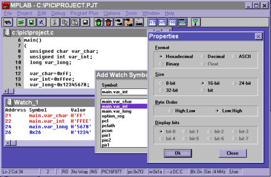
why its a good rule of thumb to use the correct method.

Watching the values of variables

Q.  How do I watch variables in MPLab?

A.   Bring up the watch window dialog by clicking on the ‘pair of glasses’ icon on the right of the menu bar. 

1.      Char variables are 8 bits can be displayed in a variety of formats. 
2.      Integer variables are 16 bits and the byte order is ‘low:hi’ in every case, as shown below. 
3.      Long variables are 32 bits and the byte order is ‘low:hi’ in every case, as shown below.

Of course, to display variables inside functions, the switch ‘-fakelocal‘ must be added to the linker options.  For this switch to work, check that you have the latest version of Hi-Tech C, v7.86pl3 or above.  This is explained in the tutorial on how to set up a project. 


Q.  How do I add another variable to a watch window?

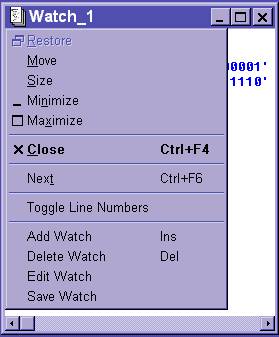
A.   Left click to the left of the ‘Watch_1’ title on the title bar, as below.

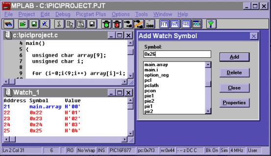
Q.  How do I watch an array of variables in MPLab?

A.   There is no built in way and in MPLab to view arrays of variables.  There is a way to get around it, illustrated by the diagram below.  To look at the array named ‘array’, select ‘main.array’ from the ‘add watch symbol’ box.  This is address 0x21, and shows array[0].  To look at array[1] enter 0x22 as the symbol.  Alternatively, to view an array of integers, increment the address by two each time.

Q.  I cannot view local variables, only global variables appear in the watch window.

A.   To display variables inside functions, the switch ‘-fakelocal‘ must be added to the linker options.  This is explained in the tutorial on how to set up a project.  For this switch to work, check that you have the latest version of Hi-Tech C, v7.85 or above.

Errors and what they mean

Q.  I get the following errors or line of errors when I compile:

::Can't find 0x64 words for psect rbss_0 in segment BANK0 (error)

A.   All this gibberish means is that theres not enough ram to fit the variables in.  In the 16F876, there are 4 banks of 96 bytes.  Move some variables to another bank, by the following method:

unsigned char array_char[79];       //goes in bank0, 96 bytes excluding overhead
bank1 unsigned int array_int[40];   //goes in bank1, 96 bytes excluding overhead
bank2 unsigned long array_long[24]; //goes in bank2, 96 bytes of 32-bit longs
bank3 float array_float[30];        //goes in bank3, 96 bytes of 24-bit floats


After this, use the variables as per normal. 

However, there are some issues with passing pointers.  For example, a function that accepts a pointer can only accept it from the same bank.  This is illustrated by the code below.

/* the following C line wouldn’t work – have to specify bank where pointer comes from, otherwise produces error “:Fixup overflow in expression”*/

//strcpy(unsigned char *to,unsigned char *from)
//works fine
strcpy(bank2 unsigned char *to,bank1 unsigned char *from)
{
   while(*to++ = *from++);    //copies strings
}
bank1 unsigned char x[3];
bank2 unsigned char y[3];

main()
{
   x[0]=’O’;x[1]=’K’;x[2]=0;  //x contains string ‘Ok’
   strcpy (&y[0],&x[0]);      //now array y contains string ‘Ok’
}


The following error is produced by passing pointers in different banks, so to fix it refer to the code above.

project.obj:33:Fixup overflow in expression (loc 0xFD2 (0xFCC+6), size 1, value 0xA1) (error)

Weird quirks of the PIC micro

Q.  PORTA doesn’t work when reading logic levels.

A.   Set it to digital mode, by setting ADCON1=7.  If its in analogue mode, it will try to do a/d operations on the port.

Q.  Port RA4 doesn’t work.

A.   Port RA4 requires a 10k pullup.  This is because it can be the input for an external timer.

Q.  My A/D doesn’t work.

A.   Check out the sample files in the c:\ht-pic\samples\ directory for an example.  For sample code for the PIC16F876/77, check out source code.

Q. Unexplained Operation and Stack Levels

A.   The PIC16F87x has 8 stack levels. This means that function calling in C can be nested up to 8 times. If function calling is nested more than this, unexplained operation will occur, because the oldest return addresses are overwritten.
Realistically, function calling can only be nested 7 times, because the interrupts use 1, if not more, stack levels. If you interrupt service routine (ISR) calls a 1 function then 2 stack levels are used just for the interrupt. Note that the ISR should never, under any circumstances, call any functions if you use Hi-Tech C. This is because the ISR has to save the function calling area, which takes lots of precious cycles.

The unexplained operation is characterised by the program jumping to functions that it shouldnt be in.

If you are unsure, always check to see how many stack levels your program uses. Unfortunately, the hardware stack on a PIC micro is not readable or accessible by the program.

The best way to check the amount of stack levels used, in Hi-Tech C, is to look at the .map file. Turn on .map files in the linking options. In MPLab, select Project..Edit Project..Node Properties..Map File On.."main.map". Manually check how many levels the function calling is nested. Allow as many stack levels for the interrupts as needed.

Another way is to manually keep a track of the stack levels with a counter. Every time a function is called, increment the counter. Every time a function is returned from, decrement the counter. Keep a track of the maximum number this counter gets to, ie:

stack_level++;if (stack_level>stack_level_max) stack_level_max=stack_level;

However, this method is not recommended. If your program is big enough to warrant checking for stack levels, it will be a royal pain to add all the calls. A #define makes it easier, also used to switch on/off the debug code, but even still, examining the .map file is much more reliable, quicker, and doesnt make the program larger.

Interesting quirks of Hi-Tech C

Generally, Hi-Tech C is a very stable, bug free compiler.  In two years of using it, I have never encountered any trouble with it.  Currently I have an 8k, 5000 line C program that works beautifully.  Make sure that you have the latest version, v7.86pl2, as some earlier versions have bugs. For example, v7.84 without the patch level 1 would sometimes branch the wrong way in an ‘if..else’ statement if the variables were in different banks.

Q.  Whats wrong with the following program?  It gives errors.

#define DOMATHS   \  <- invisible space or tabs after ‘\’ gives error
x++;              \    
y++
#include <pic.h>
unsigned char x,y;
main()
{
   DOMATHS;
}


A.   An insidious problem.  Check that theres no invisible spaces after any of the ‘\’ characters.  Do this by moving the cursor to every line with a ‘\’, and pressing the <end> key. 

Symptoms? It will generate multiple errors, with the one below as the last one.

c:\pic\main.c: 12: illegal character (0134) (error)

Serial Port with PIC

Q.  I’m using a 16F876 PIC micro to communicate to a PC with a serial port.  It wont work. How do I fix it?

A.   Here is PIC Hi-Tech C code, schematic picture and protel 99 files, plus VB 6 example code.  Download.

  1. Do you have Hyperterminal set to the correct COM port, “N,8,1” with no flow control?

  2. Get an oscilloscope, and put it in pin 3 of the serial port.  Type some characters, and you should see it coming up on the oscilloscope.

  3. Connect pins 2 and 3 on the serial cable.  This makes a loopback.  Everything you type in Hyperterm will be displayed instead of lost.

  4. The PIC sends out 5V logic levels.  The serial line operates with –13V/+13V logic levels.  Some sort of interface is needed, usually using a MAX232, MAX3222 or SIPEX232 chip.  Look up the datasheet and check that you have got it right.  Check the capacitor values.  The capacitors need to be a minimum size, anything above this will do.  33uF electrolytic caps are fine, if a bit of an overkill.

  5. Make sure that the order of the lines into the MAX232 chip is correct, as above.

  6. Check it from the micro side of things.  Run the program, downloaded above, and verify that 5V logic levels are coming out of the transmit (TX) pin.

  7. Check that the crystal speed matches the value used to calculate SPBRG and BRGH.  If you are using the ICEPIC 2000, check that the crystal speed, set in the menu options, matches the ones used to calculate SPBRG and BRGH.  Send out 0xAA, which is 10101010 in binary.  Using the oscilloscope, measure the time between the pulses and verify that they match the baud rate.

  8. If all else fails, change computer and try it on another.

Q.  My serial port sometimes dies completely, it wont receive anything more.

A.   This means you are ignoring framing and overrun error bits.  If too many characters are received before they are recorded in software, the overrun bit, OERR, gets set.  This shuts off all further transmissions.  It a wrong stop bit is received, the framing error bit, FERR, gets set.  This shuts off all further transmissions.

See the project for serial comms in the sample projects section.

Q.  I want a routine to do a serial port in software, because I’m using a low-end PIC.

Go to directory ‘c:\ht-pic\samples’ and look at files ‘serial.c’ and ‘iserial.c’.  The second file receives characters into a buffer in the background, using interrupts.  Its almost like the hardware serial port on a high-end PIC.

Interrupts

Q.  How do I use interrupts?

A.   Interrupts are very useful.  When a certain event happens – such as the logic level on a port changing, a timer overflowing or a serial character arriving – a flag is set.  For example, if the logic level on port RB0 changes, instantly the flag INTF will get set.

If the particular interrupt is enabled, the current state of the processor is saved, and execution branches to the interrupt routine. 

For example, if INTE is enabled, then it will jump to the interrupt routine as soon as INTF is set.  When it is finished, the state of the processor is retrieved and execution continues where it left off.

Here is sample code to 
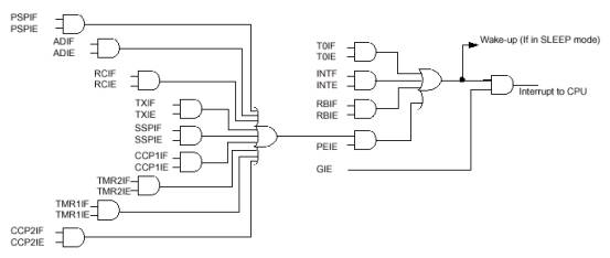
read the data line if the clock line goes low

#include    <pic.h>
main()
{
   //set up capture port interrupt
   CCP1CON=0B00000100;  //every falling edge of clock interrupts it
   CCP1IE=1;            //enable capture port interrupt on data line
   PEIE=1;
   GIE=1;               //global interrupt enable
   while(1);            //whiz around doing nothing until interrupted, it jumps to isr
}
/*note the keyword ‘interrupt’.  Hi-Tech C handles the code to save and restore the state of the micro, and the calculating the address to hook into the interrupt*/

interrupt isr()
{
   //when clock line goes low, falling edge, it reads data line
   if (CCP1IF) //clock line falling edge on CCP1IF, RC2, pin 13 on micro
   {
      CCP1IF=0;
      //read data line in here  
   }
}

Q.  My interrupt routine is not working.

A.   Try the following tips:

1.      If you put a breakpoint in the interrupt routine, and it doesn’t get there, check that every variable in the interrupt chain is enabled.  The diagram below has been reproduced from the PIC16F876 manual, from the section on interrupts.  For example, to enable the interrupt on the 16-bit timer 1 overflow, TMR1IE, PEIE and GIE must all be enabled for the interrupt to ‘interrupt to CPU’.  If PEIE or GIE is disabled, it will never jump to the interrupt routine.

2.      You must clear the interrupt flag, and in some cases read the port involved with the interrupt before exiting the interrupt routine.  Otherwise, it will keep going back into the interrupt routine continuously for ever.

3.      Important: the rule of thumb involving volatile variables:

Every variable that is referred to in ‘main()’ and ‘interrupt’ must be declared volatile   

If a variable is not declared volatile, problems will arise if it is changed.  This is because the optimiser makes the program store a temporary copy of the variable in a register.  If the interrupt comes along and changes it, even though it is changed in ram, it is not changed in the register. 

Making a variable volatile forces the program to load a fresh copy of the variable every time it wants to check it.  It also slows the program down slightly.

Here is some sample code to illustrate when to make a variable volatile:

//(c)Shane Tolmie, http://www.microchipc.com/, distribute freely for non commercial use on the condition that you include this web link somewhere in your document.
//WRONG METHOD – ‘x’ IS REFERENCED IN BOTH MAIN() AND INTERRUPT
//unsigned char x;           
//correct method
volatile unsigned char x;    
#define FALSE 0
#define TRUE 1
main()
{
   INTE=1;
   GIE=1;
   x=FALSE;
   while(x==FALSE)
   {
      //idling loop waiting for interrupt to change ‘x’
      //if x is not declared volatile, it will check its value from a temporary
      //register.  When the interrupt changes ‘x’ in ram, it will never know.
   }
   //wait for interrupt to change x to true, reaching this portion of code
}

interrupt isr()
{
   //interrupt on port RB0 change
   if (RBIF)
   {
      RBIF=0;
      x=TRUE;
   }
}


Q.  Pins RB4 to RB7 all generate a common interrupt on change, RBIF.  How do I tell what pin the interrupt came from?

A.   Keep a record of the previous state of the port, and use XOR to work out what pin changed, thus:

//(c)Shane Tolmie, http://www.microchipc.com/, distribute freely for non commercial use on the condition that you include this web link somewhere in your document.
#include    <pic.h>
main()
{
   RBIE=1;
   GIE=1;
   while(1);      //wait doing nothing
}
unsigned char prev_portb=0;
interrupt isr()
{
  //work out which pin portb changed to produce this interrupt
  if (RBIF)
  {
    RBIF=0;
    if ((prev_portb ^ PORTB) == 0B00010000)
    {
      //pin RB4 changed
      if ((PORTB & 0B00010000) == 0)
      {
            //now its 0, so its a falling edge
            //execute code here (only on falling edge)
      }
    }
    if ((prev_portb ^ PORTB) == 0B00100000)
    {
      //pin RB5 changed
      //execute code here (on pin change)
    }
    prev_portb=PORTB;
  }
}


Q.  How do I execute some code precisely every 800us at  4MHz?


A.   Use the built in timer.  Set it up so when it rolls over it triggers an interrupt.  When the interrupt is triggered, it sets flag T0IF high and executes some code. 

For this example, we will use the 8-bit timer 0, available on PIC micros.
If the micro is running at 4Mhz, it is executing instructions at clk/4 speed, or 1MIPS.  This is 1 instruction every 1us.  For 800us, we need 800 timer ticks before it rolls over.

The timer rolls over at 0xFF, or 255.  255 is smaller than 800, so use 4 lots of 200 ticks using a 1:4 prescaler.

If we want 200 ticks, and the timer counts up and rolls over at 255, we need to set the timer to 55 each time, so it will count up to 255.  Note that the prescaler is not rewritten each time – this needs to be only set once initially.  The manual seems to indicate that whenever tmr0 is rewritten, it rewrites the prescaler.  However, it means that it zeros the internal counter for the prescaler, not the actual prescaler itself.

This timing method is used in the simple multitasking technique for a PIC.  In the meantime, here are some code examples.

Method 1: execute code every 800us by using polling to check the bit in main()

//(c)Shane Tolmie, http://www.microchipc.com/, distribute freely for non commercial use on the condition that you include this web link somewhere in your document.
#include <pic.h>
#define POLLING_PERIOD 200    //with 4Mhz processor, 200us   
#define TMR0_PRESCALER 1      //gives 1:4 prescaler
//the -3 factor is to make up for overhead
//the 0xff- factor is because the timer counts *up* to 0xff
//do not change this
#define TMR0_SETTING (0xff - (POLLING_PERIOD-3)) 

main()
{
   OPTION&=0B11000000;        //turn off bottom 6 bits to configure tmr0
   OPTION|=TMR0_PRESCALER;    //set prescaler to 1:4
   while(1)
   {
      TMR0=TMR0_SETTING;
      T0IF=0;        
      while(T0IF==0);   //wait 800us for flag to go high
      //OK, tmr0 has overflowed, flag T0IF has gone high
      //this code right here is executed every 800us
   }
}


Method 2: generate an interrupt to execute code every 800us in background

//(c)Shane Tolmie, http://www.microchipc.com/, distribute freely for non commercial use on the condition that you include this web link somewhere in your document.
#include <pic.h>
#define POLLING_PERIOD 200    //with 4Mhz processor, 200us   
#define TMR0_PRESCALER 1      //gives 1:4, 800us
//the -5 factor is to make up for overhead
//the 0xff- factor is because the timer counts up to 0xff
#define TMR0_SETTING (0xff - (POLLING_PERIOD-5)) 
   
main()
{
OPTION&=0B11000000;        //turn off bottom 6 bits to configure tmr0
OPTION|=TMR0_PRESCALER;    //set prescaler to 1:4
//work out which interrupt enable bits to set by referring to diagram
T0IE=1;
GIE=1;
while(1)
{
      //idle, using interrupt to execute code
   }
}
void interrupt isr(void)
{
   if (T0IF)
   {
      TMR0=TMR0_SETTING;
      T0IF=0;
      //code right here is executed every 800us
   }
}

Q.  How do I speed up my interrupts?

A.   Here is a few tips:

  • Execute the least amount of code possible in the interrupt, do all background processing in the main(). Trigger the tasks in main() by setting a flag in the interrupt which is polled in main(). See the debt counter project for an example of this.

  • Do not use any functions in your interrupt.  This means the compiler has to save the state of absolutely everything, so it slows it down.  This is a problem of most compilers. Make everything inline or the equivalent by copying it straight in from the function. If you absolutely must have a function, to be on the safe side, use in-line assembly to call it.

  • Double check how many cycles it takes to get into the interrupt.

    Here is an example for the PIC16F87x under Hi-Tech C. To check if your interrupt is saving too much state, in MPLab, in the ROM memory window, put a breakpoint at 0x0004, the entry point of the interupt service routine (ISR). Run the program until it interrupts. Then, single step until the program gets to the first C line in the ISR. This is how many cycles it takes to get into the interrupt.

Q.  Whats wrong with the following interrupt code?

//incorrect code (if SSPIE or ADIE is being disabled/enabled in main)
interrupt void isr (void)
{
   if (SSPIF) {
      SSP_INT_SERV();
   }
   if (ADIF) {
      ADC_INT_SERV();
   }
   //...add other ints here
}

Symptoms: The program hangs after some minutes.

Use: if (ADIE && ADIF)... and etc. intead of if (ADIF). Consider what will heppen if you will disable AD interrupt for some reason (ADIE=0), and the SPI interrupt will occur. both handlers will be executed, not only the SPI handler as expected , because ADIF is set independetly of ADIE value.

//correct code (if SSPIE or ADIE is being disabled/enabled in main)
interrupt void isr (void)
{
   if (SSPIF && SSPIE) {
      SSP_INT_SERV();
   }
   if (ADIF && ADIE) {
      ADC_INT_SERV();
   }
   //...add other ints here
}

Q. How do I time exact intervals?

My favorite way to handle this 'non-commensurate' intervals problem is to steal a concept from the Bresenham line drawing algorithm.

Using the current case:

  • 4.00 MHz crystal

  • 1Mhz instruction rate

  • 256 cycles and prescaler of 64

  • each overflow of the timer represents 256*64 == 16384 microseconds

You start with a counter set to 1,000,000 (1 second in microseconds)

On each timer interrupt you subtract 16384 from the counter.

If the counter goes negative you update the time by one second and then add 1,000,000 back in to the counter.

This technique will work for any interval. It can be made perfect for intervals that have a rational relationship to the instruction cycle time, and can be abitrary close to perfect 
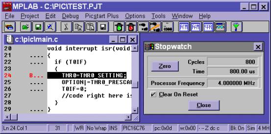
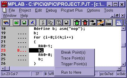
even for irrational ratios, for example a SQRT(2) Mhz crystal.

Simulator/Emulator Breakpoint Problems

Q.  I cant seem to get a breakpoint in the right spot.  It either wont put one on the line that I want it, or I cant stop on the right line.

A.   Theres a trick to setting breakpoints.  See the closing bracket ‘}’ in the code?  It hasn’t got 4 dots to the left of it.  This means that you cannot right click on that line, and put a breakpoint there.

As to making it stop on the right line, sometimes you have to add extra lines of code so it can stop exactly where you want it.  Use the #define to set ‘b’ (for breakpoint) to inline assembly language, asm(“nop”).  ‘Nop’ stands for ‘No Operation’ – it doesn’t do anything.

Emulator Problems

Q.  My circuit works with the emulator, but not if I plug in a programmed chip.

A.   Check the following:

1.      The program may be wrong.  Usually, the simulator and emulator environment has all variables are set to 0 initially.  If a program doesn’t initialise its variables, it will work in the simulator and emulator, but not on a standalone chip.

Rule of thumb: Initialise every variable to a known value before using it

2.
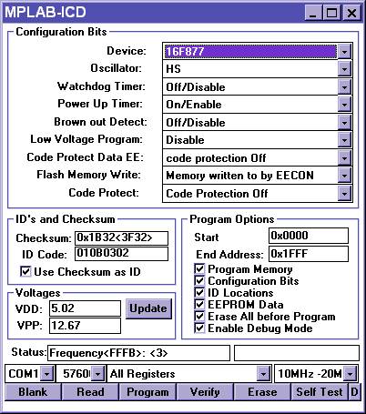
      Is the chip programmed at all?
3.      Is the chip programmed properly?  XT for <8Mhz, HS for >8Mhz, etc.
4.      Does the chip have power?  Check 5V on the correct pins.
5.      Is the reset pin pulled high with a 10k resistor?  Check that pin 1 on micro is at 5V.
6.      Is the crystal oscillating?  Get an oscilloscope and touch it to the oscillator pins on the micro.  They should both be buzzing.  If
ts not oscillating, it means either the chip is not programmed at all, or not programmed properly, the crystal is bad, the capacitors are the wrong value, or your circuit is broken or wrong somehow.  Check manual. 15pF to 33pF is about right, depending on frequency.  You can check the value of the capacitors down in the electronics lab with their component tester.
7.      I all else fails, program up a chip with the following program, then check to see if the ports B is oscillating:

#include    <pic.h>

main()
{
   TRISB=0x0;     //output
   while(1)
   {
      PORTB=0;PORTB=0xFF;
   }
}


Q.  My program works with the ICEPIC 2000 but not the ICD emulator.

A.   Add the switch ‘-ICD’ under the linker options, menu ‘project’ then ‘edit project’ then ‘node properties’. This reserves the last 256 bytes of memory, and 13 miscellaneous ram bytes that the ICD uses.  Check the compiler is v7.85 or above.  Then, match the ICD options to the box below.

These settings are the default for almost every situation, with the exception of the oscillator. 

1.      When using an external crystal with speeds of higher than 8Mhz use the settings as shown above. 

2.      Crystal speeds of lower than 8MHz use ‘XT’ for the oscillator setting instead ‘HS’. 

3.      When using a RC oscillator for the clock, made up of a resistor and a capacitor, use ‘RC’ for the oscillator setting instead of ‘HS’.

Watchdog Timer

Q.  What is the watchdog timer and why do I want it?

A.   The watchdog is a good way to ensure that the microprocessor does not freeze forever from a crash, due to a bad power supply or a rogue program.  When the chip is programmed, the watchdog timer bit is enabled.  It cannot be turned off in software, in case a rogue program overwrites it.  If the timer is not reset regularly with a CLRWDT() instruction, it will reset the micro.  This will happen within 18ms to 2 seconds, depending on the prescaler selected.


Q.  After I programmed my PIC, it kept restarting itself every couple of seconds.

A.   Have you got the watchdog timer bit set?  The watchdog is a good way to ensure that the microprocessor does not freeze forever from a crash.  When the chip is programmed, the watchdog timer bit is enabled.  It cannot be turned off in software, in case a rogue program overwrites it.  If the timer is not reset regularly with a CLRWDT() instruction, it will reset the micro.  This will happen within 18ms to 2 seconds, depending on the prescaler selected, and on the temperature.

It is interesting to note that it is possible to make a PIC into an accurate temperature sensor using the time of the watchdog timeout to sense the temperature.

The advantage of using a watchdog timer is that the micro is protected from crashing forever due to a bad power supply or a rogue program.

Useful techniques for using C with PIC

Q.  Have you got any delay routines?

A.   Its important to have accurate delay routines.  Delay routines written in C aren’t accurate – depending on optimisations, they can vary.  That’s why some of 
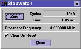
the routines have inline assembly.  Delay routines are available for download.

Q.  How do I measure the time code takes?

A.   If you’re using the simulator or the ICEPIC 2000, bring up the stopwatch under menu ‘windows’.  Put breakpoints before and after the section of code, and measure the time.

The MPLAB-ICD doesn’t have a stopwatch.  Add a piece of code to read out the value of timer 1 at the start of the code, then check it again at the finish.  The timer increments at the same frequency as instructions executed.  Do some maths and you have the time in clock cycles that the code takes.

Q.  How do I make a variable oscillate, ie: go 1-0-1-0

A.   Do the following code:

unsigned char x;
x=1-x;            //every time this statement is executed, x goes 1-0-1-0-1-0 etc


Q.  How do I reset the micro?

A.   One way is to reset all variables to their defaults, as listed in the PIC manual.  Then, use assembly language to jump to location 0x0000 in the micro. 

#asm
ljmp 0x0000
#endasm

This is quite safe to use, even when called within interrupts or procedures.  The PIC 16x series micros have 8 stack levels.  Each time a procedure is called, one stack level is used up for the return address.  It is a circular buffer, so even if the micro is 7 procedure levels deep and in an interrupt when a reset is called, this is the new start of the stack buffer, and the micro will continue as per normal. 

Another way is to set watchdog the timer when the chip is programmed, and use CLRWDT() instructions all through the code.  When you want the micro to reset, stop clearing the watchdog bit and the micro will reset after around 18ms to 2 seconds depending on the prescaler.

Q.  Theres a variable in the PIC manual that the compiler doesn’t recognise, even though I used the same name.  How do I tell what the compilers called it?

A.   Go to directory c:\ht-pic\include\ and look at the header files.  These give the names that the compiler gives to the internal variables.  This is extremely useful for finding out exactly what variables are available in C.  Heres some example code from the header file, pic1687x.h for the PIC16F87x micro:

/*
 * Header file for the Microchip
 * PIC 16F873 chip
 * PIC 16F874 chip
 * PIC 16F876 chip
 * PIC 16F877 chip
 * Midrange Microcontroller
 */
//[added for FAQ] we can see that the compiler has called PORTA by the same name as the manual
static volatile unsigned char PORTA @ 0x05;
//[added for FAQ] ... the listing continues on ...
/*      PORTA bits      */
static volatile bit     RA5   @ (unsigned)&PORTA*8+5;
static volatile bit     RA4   @ (unsigned)&PORTA*8+4;
//[added for FAQ] we now know that each bit in PORTA is called, for example, RA5, as per manual
//[added for FAQ] ... the listing continues on ...

Q.  Whats the rule of thumb for timeouts?

A.   Rule of thumb: every time a program waits for an operation that could fail, have a timeout to exit it after too much time.  For example, reading in a byte with SPI.  There is the clock and data line, and a byte with 8 bits is read into the micro.  If the sender of the byte stops halfway through, there is four garbage bits remaining.  Later on, after 5 minutes, the sender sends a new byte.  Everything is now out of sync, with the first half going into one byte, and the last half going into the next.

Use the following code to implement timeouts. 

//(c)Shane Tolmie, http://www.microchipc.com/, distribute freely for non commercial use on the condition that you include this web link somewhere in your document.
// example of how to use timeouts:
unsigned int timeout_int;
//for max 491512us timeout @ 8Mhz
//for max 245756us timeout @ 16Mhz
timeout_int=timeout_int_us(500);
while(timeout_int-- >= 1)
{
   if (x==y) break;           //typical overhead for checking ring buffer
}
if (timeout_int<=2) { //theres been too much time elapsed }
//for max timeout of 1147us @ 8Mhz
//for max timeout of 573us @ 16Mhz
timeout_char=timeout_char_us(500);
while(timeout_char-- >= 1)
{
   if (x==y) break;           //typical overhead for checking ring buffer
}
if (timeout_int<=2) { //theres been too much time elapsed }
/*
Time taken: optimisations on:       9cyc/number loop, 4.5us @ 8Mhz
            with extra check ie:    && (RB7==1), +3cyc/number loop, +1.5us @ 8Mhz
Formula:    rough timeout value = (<us desired>/<cycles per loop>) * (PIC_CLK/4.0)
*/
#define LOOP_CYCLES_CHAR      9     //how many cycles per loop, optimisations on
#define timeout_char_us(x)    (unsigned char)((x/LOOP_CYCLES_CHAR)*(PIC_CLK/4.0))
#define LOOP_CYCLES_INT       16    //how many cycles per loop, optimisations on
#define timeout_int_us(x)     (unsigned int)((x/LOOP_CYCLES_INT)*(PIC_CLK/4.0))


Q.  I need more space in the micro – 8k is not enough for a 16F876. 

A.   You’ve done well.  One thing to check is that you havnt got any orphaned functions which are never called.  Hi-Tech C includes the code, even though it is redundant.  To automatically check for this, set the warning level to –9 (negative nine) under menu ‘Project’ then ‘Edit Project’ then ‘node properties’.  This introduces all sorts of warnings.  Most of them can be ignored, except the one:

::function _myfunction is never called (warning)

This means that the code for the function ‘myfunction’ is included somewhere in your code, but it is never called.  If you’re not going to use it, comment it out.

You must have your project set up to 'compile at once' rather than 'linked' for the compiler to give this information. See tutorial.

Q.  Can I use printf() when communicating with a PC computer via the RS232 serial port?

A.   You can use printf() to write to the USART on a PIC micro if you define your own putch() routine and #include the correct header file.  It uses an extra 650 words of program memory.  See the sample code here.

Q.  Why cant I print long (32 bit) variables with printf()?

A.   Add the switch ‘-lf’ to the ‘additional command line options’, under menu ‘Project’ then ‘Edit Project’ then ‘Node Properties’.  This uses up a additional 1600 words of rom space, but it allows printf to print longs.

Q.  How do I store large amounts of data?

A.   Use EEPROM or the Dataflash available from Microchip or Atmel.   Capacities range from 1Kbyte to 4Mbyte non-volatile chips.

Hardware for PIC

Q.  Can I control 2 LEDs from one port?

A.   Yes.  The only catch is that one has to be on at any time.  Connect the 2 LEDs in series, between the 5V and GND rails.  Attach the port to the middle between the LEDs. Connect a current limiting resistor in series between the VCC rail and the top LED, and between the GND rail and the bottom LED. Different color LEDs require different voltages acorss their terminals, read the datasheet.

Q.  I want to protect my circuit from overcurrents and shorts.

A.   Get a polyswitch, available from, among others, the manufacturer RayChem.  See http://www.raychem.com/, search for “miniSMDC075”.  These are tiny autoresetting fuses that limit the current to no more than a certain value.

Q.  How do I save power in my embedded micro system?

A.   There are many methods to reduce the power consumption of a circuit with a micro in it.

1.      Use the lowest clock frequency possible.  For PIC micros, the power consumption seems to rise as the square of the frequency.
2.      Put the micro into sleep mode.  It can wake itself up when an internal timer rolls over.  Be careful to complete all operations, in software and hardware, before putting the micro to sleep.  For example, if a serial character is only half received in hardware, wait until it is fully received before shutting down.
3.      Switch off external peripherals when they are not in use.  For example, have one pin on the micro connected to the standby pin of the serial chip.  You could even power external chips off the micro, as the micro can source 20mA, and simply switch off the port when it is not in use.
4.      Use the lowest voltage possible.  In saying this, be very careful to look up the voltage range for each chip when using it in your circuit.  An example is a 5V embedded datalogger, which had a 4Mbit flash chip in it.  Instead of using the AT45D041, the 5V part, the AT45DB041, the 3.5V part, was used.  It seemed to work perfectly.  The only problem was that every 20th page of data read from the chip was completely corrupted.

Q.  My PIC sometimes resets by itself.

A.   Bad power?  Brownouts?  Put a decoupling cap as close to the power supply as possible, so when it switches it doesn’t brown itself out.  0.1uF for <8Mhz, 0.01uF for >8Mhz.

Bootloader for PIC16F876

Q.  How do I do a bootloader for the flash based 16F876?

A.   Although code is available from Hi-Tech, this is a modified and enhanced version that doesnt need RB0 - it uses timeouts, so the code is loaded within 1 second of powerup. It also handles config bits properly, and programs the EEPROM also. See sample code archive here.

Simple Multitasking Kernel for PIC under Hi-Tech C

Q.  How do I handle many things at once on a PIC?  I want a simple multitasking system.

A.   See here for a big explanation of this.

Tips for using the PICSTART Plus Programmer

Q.  The programmer doesn’t seem to work – it doesn’t program

A.   Sometimes this happens, maybe MPLab has got something wrong with it or the programmer itself has crashed.  It can crash – its running code just like the computer.  Pull the plug out of the programmer, shutdown the computer and restart it, then retry it.  This usually fixes the problem.

Q.  How do I embed configuration words for the programmer into my C program
Q.  MPLab always loses my settings for the PICStart plus programmer when I exit

A.   Use the __CONFIG(); macro in your C code, after #include<pic.h> to set these bits.  First, look up the appropriate include file for your micro.  Then compare this to the include bits in the PIC .pdf manual. For the PIC16C76, <pic.h> includes file pic1677.h, found in c:\ht-pic\include\.  At the bottom of the file,these lines appear:

//look up datasheet for explanation of terms
#define CONFIG_ADDR 0x2007
#define FOSC0 0x01
#define FOSC1 0x02
#define WDTE 0x04 //Watch Dog Timer (Enable low) - (include to disable)
#define PWRTE 0x08 //PoWeR Up Timer (Enable low) - (include to disable)
#define BODEN 0x40 //Brown Out Detect ENable - active HIGH (include to enable)
#define RC (FOSC1 | FOSC0)
#define HS FOSC1
#define XT FOSC0
#define LP 0x00
#define CP0 0x1510
#define CP1 0x2A20
/* code protection */
#define UNPROTECT (CP0 | CP1) // unprotected
#define PROTECT50 CP1 // upper half program memory code protected
#define PROTECT75 CP0 // upper 3/4 program memory code protected
#define PROTECT 0x00 // all memory code is protected

Thus, to make PICStart Plus default to HS, Watchdog On, Power up time enabled, Brown Out Timer enabled, and Unprotected, use the following lines:

#include<pic.h>
__CONFIG(HS | BODEN | UNPROTECT);

Be careful of PWRTE. According to the PIC manual, this is active low, so missing it out turns the power up timer on. Including it turns it off. This is the same for WTDE.

Some compilers recommend linking the fuse names with logical "OR", the symbol "|". Other compilers recommend linking the fuse names with logical "AND", the symbol "&".

Tips on using Libraries with MPLab

Q.  What is a library, consisting of a ".lib" file, and how do I use it?

A.  Normally, most people have a library of commonly-used routines that are always included in every project they do.

For example, there is the following files:

·        delay.c - delay routines in C such as DelayMs(x)
·        delay.h - header file for delay.c
·        serial.c - serial RS232 routines such as putch() and getch()
·        serial.h - header file for serial.c

One method of using these routines could be to include these files in your project. Put the following lines in your main .c file:

#include "delay.h"
#include "delay.c"
#include "serial.h"
#include "serial.c"

main()
{
}


However, this method has one key disadvantage: even if a routine is not used, it will still take up memory in the final compiled .hex file.

Using a library solves this problem. Once you have made a library out of your commonly used routines, the linker picks out the necessary routines and includes them in the final .hex file.

Q.  How do I make a library file?

View the latest answer to this question on MicrochipFault.com; tags

Lets say I have a number of modules, each one an object file, ending in ".obj". I can put these in a library by executing the following at the dos prompt:

libr r xx.lib i2c.obj ser_877.obj delay1.obj

I now have a library called xx.lib which can be included in my project. Under 'Project' and 'Edit Project' and the 'Library Path' box, enter the path to xx.lib. If it gives an error, see here. Alternatively, use 'Add Node' to add the ".lib" file to the project.

Q.  I make a library file ending in ".lib" but I cant tell MPLab how to get to it

View the latest answers to this question on MicrochipFault.com; tags

A.  Under Project..Edit Project, click in 'Library Path'. If you see the following error message, you have set up the project incorrectly.


You need install the 3 languages: under "Project..Install Language Tool" for compiler, Assembler and Linker, all select "c:\ht-pic\bin\picc.exe".

Select "Project..New project (or Edit Project)" then click on "node property"

***[.HEX] : select language tool: Linker
***[.C]: select language tool: Compiler

If the language tool for ***[.HEX] is set to Compiler, then this means the linker is never used, and no libraries or additional C files can be added.

Serial Numbers with Hi-Tech C

Q.  How do I add serial numbers to a program coded in Hi-Tech C?

View the latest answers to this question on MicrochipFault.com; tags

A. Use the following to preserve the Rom location for a serial number:

;Reserves 4 bytes for Serial Number programming
;To be placed at 0x0FFC to 0x0FFF with the PICC option -L-Ppreserve=ffch
;The 0x0FFF=4096 is for a 4k micro, a 2k or 8k micro would be different

psect preserve
retlw 0xFF ;Serial No
psect preserve


The "-L-Ppreserve=ffch" must be entered in the option field in MPLAB for the HiTech Linker to place the code segment at the specific address.

The code is saved as an *.as file and included as a node in the MBLAB project and uses the PICC Assembler to compile. Remember to set the Assembler in the Language tool to Picc.exe.

Incremental Compiles with Hi-Tech C

Q.  Under Hi-Tech C and MPLab, every time I recompile, it recompiles everything and then links it. How do I do incremental compiles?

View the latest answers to this question on MicrochipFault.com; tags

A. Add the line 'c:\ht-pic\include' under 'include path' in the 'edit project' dialogue to enable incremental compiles.


You must already have the 'language tool' under the root node set to 'PIC C Linker', not 'PIC C compiler'. Add each source file to the list to be compiled and then linked.

PIC12F672 and OSCCAL

Q. How do I set the OSCCAL register in Hi-Tech C for the PIC12F672?

View the latest answers to this question on MicrochipFault.com; tags

A. If the built-in 4Mhz RC oscillator for the PIC12Cx67x is used, it can drift with temperature variations. The oscillator calibration speed is trimmed by setting register OSCCAL at run time. The top ROM byte in memory is read to obtain this value at runtime.

Looking in the header file, c:\htpic\include\pic1267x.h, we find the following lines, in different parts of the header file

static volatile unsigned char bank1 OSCCAL @ 0x8F;

#if defined(_12C672) || defined(_12CE674)
#define _READ_OSCCAL_DATA() (*(unsigned char(*)())0x7FF)()
#endif


Thus, use the following C line at the start of the program:

OSCCAL=_READ_OSCCAL_DATA();

If you are using a flash -F- part or a UV-erasable -JW- part, remember to record the value of the highest ROM address. It will be in the form retfw N where N=calibration value. For example, if N=0x90, the instruction will be 0x3490.

I used seven PIC12C672-JW parts in development. The OSCCAL values that I recorded for them were 0x90, 0x94, 0xB0, 0x84, 0xC8, 0xB0, 0xC0. This illustrates the fact that there is process variation among batches of PIC micros.

If you lose the value of OSCCAL for a particular JW part, you can retrieve it, with effort. Write a little routine to output 10kHz pulses. Alter the OSCCAL value until the pulses are indeed 10kHz as viewed on an oscilloscope.


This site is non-profit. Ad revenue almost covers hosting costs.

We welcome any suggesions or comments! Send them to Shane Tolmie on support@microchipc.com. This site is a completely separate site to www.microchip.com, and is maintained independently of Microchip Ltd., manufacturers of the PIC micro. All code on this site is free for non-commercial use, unless stated otherwise. Commercial use normally free, however, it is prohibited without contacting support@microchipc.com for permission. All content on this site created by Shane Tolmie is copyrighted by Shane Tolmie 1999-2009. Click to advertise on this website - $29.90 for a banner ad which will reach 55,000 user sessions per month. One months free trial!